| |
|
 Oxygen Plasma Etching and Treatment Oxygen Plasma Etching and Treatment
|
Sample cleaning for SEM, TEM, FIB
|
Photoresist ashing, descum, MEMS
|
|
산소 플라즈마 에칭, 표면 처리
|
SEM, TEM, FIB 샘플 클리닝
|
포토레지스트 에싱, 디스컴, MEMS
|
|
 Microfluidic PDMS, glass slide, lab-on-chip Microfluidic PDMS, glass slide, lab-on-chip
|
Wire bonding/flipchip/underfill/encapsulation
|
Next generation of lithography system
|
|
마이크로플루이딕, PDMS, 유리슬라이드, 랩온 칩
|
와이어 본딩, 플립 칩, 언더필/다이본딩, 인캡슐레이션
|
차세대 리소그래피(NGLs) 장치
|
|
 Metal to metal, or composite bonding Metal to metal, or composite bonding
|
Plasma treatment for polymer
|
Thin film deposition, surface analysis
|
|
금속-금속, 복합소재 본딩
|
폴리머 플라즈마 처리
|
박막 증착, 표면 분석
|
|
 Semiconductor inspection/review/metrology Semiconductor inspection/review/metrology
|
Contamination removal on XPS/SIMS/AES
|
|
|
반도체 검사, 리뷰, 계측
|
XPS, SIMS, AES의 오염 제거
|
|
| |
|
|
플라즈마 클리닝을 통해 UHV에 빠르게 도달하며, 진공 수준을 향상시킨다.
|
HV, UHV, and XHV 시스템 정의 :
A regular roughing pump can usually achieve a vacuum level around 10-3Torr range
in a short amount of time. To further reduce the pressure, a multistage vacuum pump system
is required. High Vacuum (HV) usually stands for the pressure between 10-3 Torr to 10-8 Torr range. Once the pressure reaches below 10-8 Torr range, it can be considered as Ultra High Vacuum (UHV). If the pressure is further reduced to below 10-12 Torr range, it will enter
the Extreme High Vacuum (XHV) range.
|
| |
ultra-high vacuum (UHV), 또는 그 이상에 도달하기 :
UHV에 도달하는 기존 방법 :
UHV is important for surface science research because the residual gas in the chamber can contaminate the sample surface.
UHV is also critical for charged particle accelerators, electron, ion, X-ray and EUV imaging and analysis equipment to minimize
the scattering of the ions, electrons, X-ray and EUV photos with the residual gas atoms or molecules in the chamber.
The roughing pump can quickly remove the gas in the chamber from the atmospheric pressure. Gas flow is mostly viscous
in the low to medium vacuum. Chamber volume and pumping speed determine the pump-down time in the low to medium vacuum.
Once the pressure reaches the high vacuum range, then the outgas from the chamber wall or the internal components will dominate.
In this pressure rane, the residual gas particles move randomly in the chamber because of the high mean free path. Factors such as
the surface area of the chamber wall and other internal components, types of the materials, and the pumping speed of the vacuum system determine the ultimate pressure and the pump-down time.
There are three major sources of outgassing inside a vacuum chamber: water, hydrocarbon, and fluorocarbon. Long-chain hydrocarbon
and fluorocarbon usually have low vapor pressure. For a certain amount of outgassing source, the lower the vapor pressure, the longer
it takes to outgas. High temperature can increase the degassing rate. Baking is the commonly-used method to increase the degassing speed
in a vacuum chamber. The vapor pressure will increase at a high temperature for the long-chain polymers.
|
| |
플라즈마 클리닝 소개 :
Plasma is also called the fourth matter. It consists of electrons, ions, neutral gas species. If oxygen or a mixture of oxygen with one or
more innert gases is used to generate the plasma, it can also generate chemically reactive atomic oxygen and ozone. To generate the plasma,
an external electric field (AC or DC) will accelerate the electrons to an energy that is high enough to ionize the process gas. Then the high energy electrons will transfer the energy to the atoms and molecules of the process gas through impact ionization or dissociation. The energized process gas atoms or molecules will eject one or more electrons and becomes ions. The excited molecules can also break apart and generate smaller fragmented atoms or molecules. Some of the excited atoms and molecules may also emit higher energy UV photos. It is called plasma photoemission.
|
| |
어떻게 플라즈마 클리닝이 UHV 챔버의 진공 속도를 높이는가 ?
Plasma can be generated and sustained in the pressure range from 0.5mTorr to several Torr in the downstream chamber. It's fairly convenient
to add a plasma cleaning step right after the initial chamber evacuation step. Remote plasma sources like EM-KLEEN or SEMI-KLEEN can be
directly hooked up to the vacuum chamber with a CF2.75" flange or NW40 flange. It's possible to add an isolation valve between the remote plasma source and the UHV chamber. So the plasma source will only open to the main UHV chamber during the plasma cleaning process.
Once the plasma cleaning is finished, the isolation valve can be closed off to the plasma source. Our EM-KLEEN and SEMI-KLEEN remote plasma source can be operated when the chamber is pumped by a roughing pump only (turbopump off) or with the turbopump turned on. We usually recommend running the plasma source with turbopump in operation. If the turbopump is in operation, the pressure range inside the main chamber during plasma cleaning is usually around 0.5mTorr to 2mTorr, which is safe for most of the turbopumps. The gas flow rate is somewhere between several sccm to tens of sccm depending on the pumping speed. Here are several possible mechanisms that plasma cleaning can speed up the pump-down process.
1) Desorption, dissociation, and chemical reaction with water, hydrocarbon and fluorocarbon contamination inside the UHV chamber. When the vacuum chamber is vented with air, the internal surface can easily be coated with tens to hundreds of layers of water molecules. Besides water, hydrocarbon and fluorocarbon can also be introduced into the chamber by ambient air, samples, and other internal components. Water is usually the dominating residual gas in the initial phase. Once the pressure reaches below 10-8 Torr range, hydrocarbon and fluorocarbon can become
more and more important sources of outgassing. In certain operating conditions, plasma generated from the external remote plasma source like
EM-KLEEN and SEMI-KLEEN can diffuse into the downstream chamber and sustain a plasma in the downstream chamber. So the energy can be directly transferred from the external rf power supply into the main UHV chamber through the plasma. Once the plasma is generated in the main UHV chamber, external rf energy will create high energy electrons, ions, neutral radicals, and UV photons. When the high energy particles hit the chamber wall, they can knock out the absorbed water, hydrocarbon, and fluorocarbon contaminants from the internal surface of the vacuum chamber. In the process, some of the high chain hydrocarbon and fluorocarbon can be broken down into smaller fragments, which usually have a much higher vapor pressure than the original long-chain polymers. The desorption of the contaminants from the chamber wall and the dissociation of the bonds in the molecules are physical processes. They can happen even when chemically inert gas, such as argon or nitrogen, is used to generate the plasma. If oxygen or a mixture of oxygen is used to generate the plasma, radical atomic oxygen or ozone can be created. They can chemically convert the hydrocarbon into COx and H2O. The desorption of the water, hydrocarbon, and fluorocarbon molecules happens on the surface. The dissociation or chemical etching of the hydrocarbon and fluorocarbon molecules happens mostly inside the bulk of the plasma volume after the molecules have been desorbed from the surface. The low-molecular-weight by-products from the dissociation process and the chemical reactions are usually much easier to be pumped out due to higher vapor pressure.
2) Purge the water out of the UHV chamber. During plasma cleaning, a certain amount of external gas will leak into the plasma source to generate the plasma. The gas flow rate may range from several sccm to tens of sccm. Once the water is desorbed from the internal surface of the UHV chamber, it may take a long time to pump them out because the water molecules move randomly in the high vacuum due to the long mean free path in the high vacuum pressure. This is called molecular flow compared with the viscous flow in the low vacuum pressure. In the molecular flow scenario, the chance of the desorbed water molecules hitting the internal surface of the UVH chamber and getting absorbed again can be much higher than the possibility of entering the vacuum pump and getting pumped out. Leaking some dry gas into the vacuum chamber can increase the pressure and change to viscous flow, which can help to remove the desorbed water molecules out of the UHV chamber faster. The purging gas flow admitted by the plasma cleaning process can also help the vacuum pump to remove the condensed water inside the vacuum pump. It has a similar effect as opening the gas ballast valve on the vacuum pump.
|
| |
실험 결과 :
Experiment setup
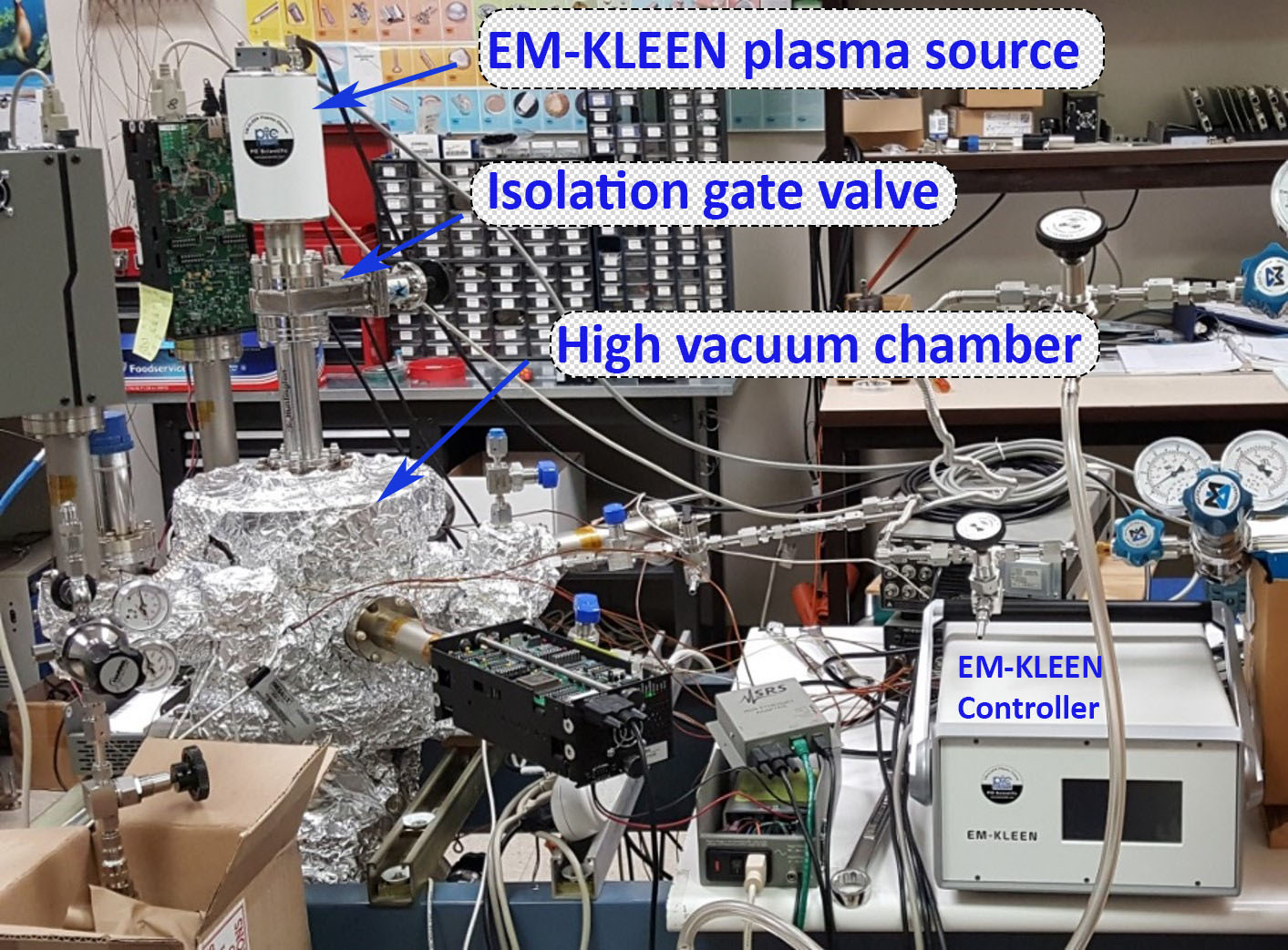
In the following test, an EM-KLEN plasma source was installed on the top of a small high vacuum chamber. A UHV compatible isolation valve isolates EM-KLEEN from the main chamber. The isolation valve only opens during plasma cleaning. Once the plasma cleaning is finished, the isolation valve will close and reduce the leakage from the plasma source to the main UHV chamber.
RGA spectrum before and after plasma cleaning
Several RGA were installed on the UHV chamber to measure the residual gas species inside the vacuum chamber before and after the plasma cleaning step. Water, hydrocarbon and fluorocarbon peaks are usually very prominent before chamber baking. It may take more than a week of chamber baking and pumping at an elevated chamber temperature of 250 0C. But a 25-minutes plasma cleaning with ambient air greatly reduced the water content and almost completely removed hydrocarbon and fluorocarbon peaks from the RGA spectrum.
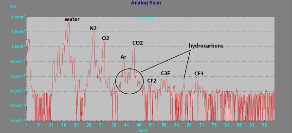
RGA spectrum before plasma cleaning
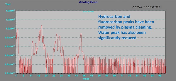
RGA spectrum after 25-minutes ambient air plasma cleaning
Reduction of the pump-down time and improvement of the vacuum level.
Plasma cleaning significantly reduces the pump-down time and improve the vacuum level
Before the plasma cleaning method was implemented on the UHV chamber, the chamber could only reach 1.1X10⁻⁷ Torr pressure while the heating was still on the chamber even after seven days of baking and pumping. It means the water, hydrocarbon, and fluorocarbon still existed in the chamber at a relatively high concentration even after seven days of baking and pumping. Then the chamber was vented to the atmospheric pressure again to install the EM-KLEEN plasma source. A 4-hour long plasma cleaning for the vacuum chamber with 80% argon and 20% oxygen as the process gas was carried out right after the initial chamber pump-down. The chamber was then baked for two days after plasma cleaning. The chamber pressure reached 2.4X10⁻⁸ Torr with heating still on after 4-hour of plasma cleaning and two days of baking. Even though the baking time was reduced from seven days to two days, the vacuum level improved by more than four times. Plasma cleaning reduced the water, hydrocarbon, and fluorocarbon contamination inside the UHV chamber at a much higher speed than regular chamber baking.
Visulization of the surface cleaning effect
The effect of the plasma cleaning on the UHV chamber has been validated by analyzing the composition of the residual gas inside the UHV chamber before and after plasma cleaning. In order to visualize the plasma cleaning effect, a used RGA shield grid contaminated with a thick layer of hydrocarbon was placed in the UHV chamber for plasma cleaning. The black carbon layer on the surface was deposited by low energy electron dissociation with hydrocarbon gas in the chamber when the filament in the RGA is turned on. The plasma cleaned RGA part is shown on the right. It proves that plasma cleaning with oxygen or a mixture of oxygen plasma can effectively remove the carbon contamination on the surface of the internal components inside the vacuum chamber.
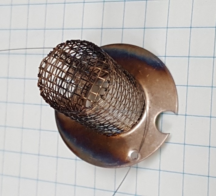 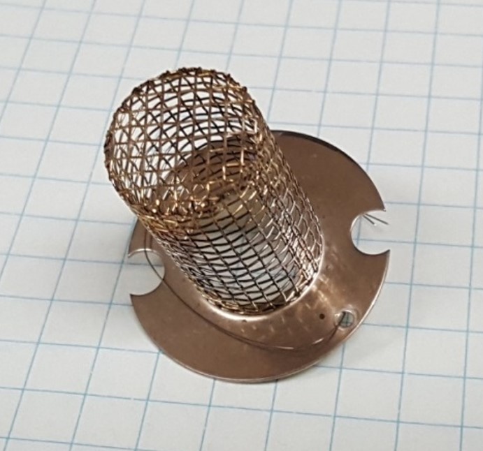
Plasma cleaning for contaminated RGA grid, contaminated one on the left, plasma cleaned on the right.
Plasma surface cleaning effect characterized by X-ray photoelectron spectroscopy
In another study, SEMI-KLEEN plasma source was installed on the load lock chamber of an XPS system. In step 1, XPS system measured the composition of a clean InGaAs sample surface. In step 2, the sample was cleaned by a 2-second remote hydrogen plasma. Then the surface was analyzed by XPS system again. There is no carbon or oxygen contamination added to the surface by the hydrogen plasma cleaning step. In step 3, the cleaned InGaAs sample was exposed to ambient air for 1 hour. The subsequent XPS measurement indicated that the surface had been contaminated by carbon and oxygen. In step 4, the contaminated InGaAs samples was cleaned by 2-second hydrogen plasma again.
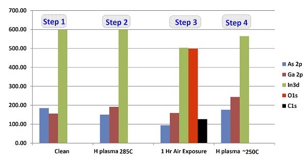
The data proves that there are plenty of hydrocarbon contamination in the ambient air. So venting the chamber with ambient air will recontaminate the chamber with hydrocarbon contaminations. It also proves that remote plasma cleaning can effectively remove the contamination on the surface of samples or on the surface of internal components in the UHV chamber.
Conclusions
Adding a plasma cleaning step right after the initial low vacuum pump down can significantly reduce the overall pump-down time and improve the ultimate vacuum level. High energy particles generated by the plasma can knock out the absorbed water, hydrocarbon and fluorocarbon contaminations on the internal surface of the chamber wall and of the internal components. Plasma created with oxygen gas or a mixture of oxygen gas can also chemically convert the long-chain organic polymers into high vapor pressure by-products that can be easier to be pumped out. The relatively high gas flow during plasma cleaning can also purge out the water molecules trapped in the UHV chamber. It can also remove the water condensation inside the vacuum pump.
Click here to download the PDF version of the articles.
Related products
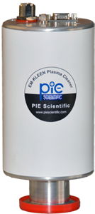 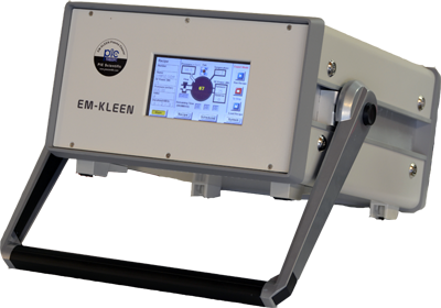
EM-KLEEN remote plasma source and controller
|
|
|


